Objective
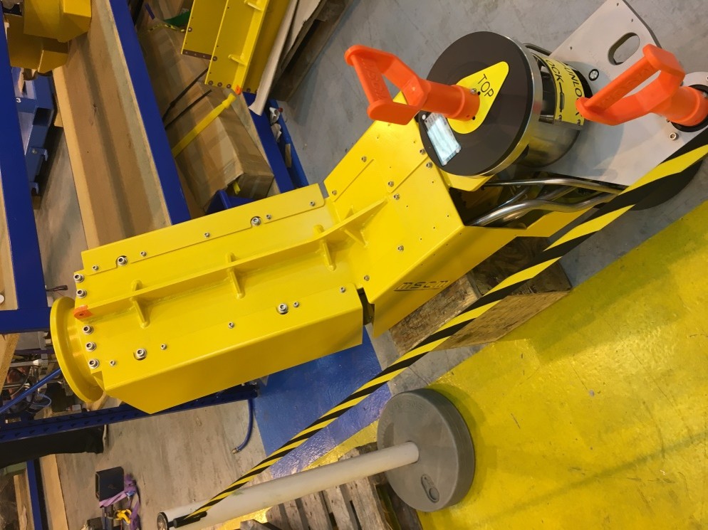
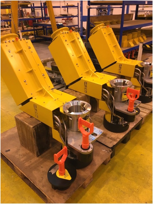
Deliver a robust HFL solution capable of repeated wet-mate cycles with low make/break forces, positive location on the stab plate, and controlled hose/tube curvature during installation. The design needed to accommodate different service configurations (chemical injection, MEG, hydraulic supply/return) while sharing the same structural backbone and handling approach.
Key Design Features
- Steel-Tube / Hose variants: options for STFL or hose bundles with PBOF capability; Minimum Bend Radius (MBR) governed by formed guides and clamp spacing.
- Stab-Plate Module: guided alignment pins, funnel lead-ins, and keyed ports limit cross-connection risk; corrosion-resistant materials and sacrificial anodes provision.
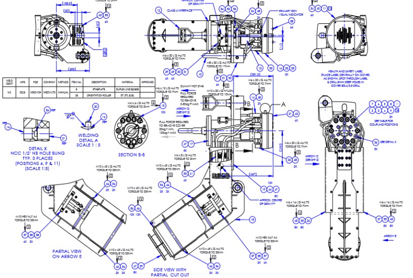
- ROV Operability: dedicated Class-4 torque bucket, softline lift points, QR grab handles, large labels/windows for port ID, and glove-friendly fasteners.
- Structural Backbone: welded/fabricated arm with stiffeners, shear keys and bumper faces to protect connectors; designed for lift, impact, and hydrodynamic loads.
- Sealing & Cleanliness: parking caps with pressure compensation, particulate controls, and wet-mate connector cleanliness controls (filters, caps, covers).
- Through-life Maintenance: modular cartridge sub-assemblies reduce strip-down time; all wear items accessible with standard ROV tooling.
Engineering Approach
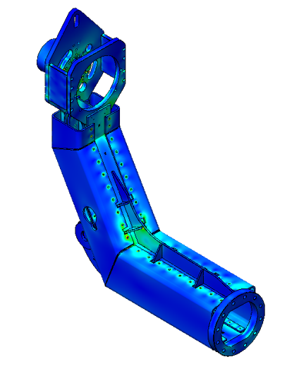
Loads & Analysis: Static strength and fatigue checks under lift, deck handling, and current-induced loads. FEA on the elbow & base frame, fastener sizing to Eurocode/ASME, and weld design with throat & fatigue class selection.
Hose/Tubing Integrity: Routing designed around manufacturer MBR, clamping at nodes to control ovalisation; MCT / bend restrictors sized using pressure + temperature envelopes.
DFMEA & Hazops: Focus on mis-mate prevention, contamination, parking mis-use, hose kinking during over-boarding, and accidental release. Mitigations include keyed plates, strain-relieved parking, and lift-line geometry that keeps the C.G. below the lift point during splash-zone transit.
Standards & Practice: Designed in line with API 17E/17D guidelines for subsea production systems, typical ROV tooling standards, and DNV-RP fatigue assessments for welded details in seawater.
Outcome
- Common platform covers multiple fluid services and port counts, reducing BOM variants by ~30%.
- Installers reported improved first-time alignment and lower make forces at the stab plate.
- Deck handling time reduced via clearer marking, balanced lift geometry, and simplified parking.
Gallery